Tuesday, January 31, 2012

Cantilevers, Design + Structure

Cantilevers Cantilevers Cantilevers...
Since I'm doing a cantilevering structure,
I look into long and slender cantilevers for my design and after much research I came across a hummingbird.


I'm intrigued by the hummingbirds structure, and it's body and beak ratio.
I understand that simply scaling up the structure will not result into a structurally stable design on an architectural scale. However, with further investigation I think it is plausible to use the hummingbird skull+beak formation to develop my overall design.


Left: Preliminary formation
Right: Developing a framework from
(Sorry, I'm not quite sure why the photos are sideways)

For the Steel Structure I will look into and investigate the structure of plant stems. Experiments have shown that hollow stems are remarkably light yet very strong, which is an important component of a cantilevered structure. The transverse septa at nodes in stems play a vital mechanical role-they resist cross-sectional rupturing when sterns are bent.


Structures such as the tree fern stem shown at left, lack any form of major mechanical supporting tissues but is based on a series of Inverted 'V' - shaped fiber caps, delimiting the central hollow from the otherwise fibrous stem. These trees are capable of growing to up to 20-30 meters tall.


Wall Thickness and Hollow Centers


The stem of Equisetum shown above is an example of a non-woody species, but hollow-centered, adding strength to the structure


Transverse Section of a Horsetail Fern


As for model and renders....I'll post that later...

-Liz

Back to Square One!

As I was continuing my research on snakes, quadrate bone connections and the idea of responsive kinematics, I found myself continuously getting stuck on one specific design element. This eventually drove me to simply trying to design a connection or mechanism based upon a quadrate bone system, putting me completely off track of where I wanted to be at that point in time. I decided to take a step back, trying to understand what I wanted to achieve with my design. The original idea was a public, recreational outdoor space that would essentially take different form and create different program based upon its surrounding environment. The concept still seemed like a solid idea so I began exploring it once again but from a different angle. This time solely looking at responsive kinematics in architecture.

I began doing some more research on ideas and precedents of kinetic architecture and looked through Robert Kronenbourg's "Transportable Architecture 2 and 3". This gave me some really interest ideas of how I could re-purpose a kinetic system within my design to have it work the way I wanted it too. I began to run with it, thinking on the premise that if my structure could directly influence one form, its transformation through motion would inevitably create a completely new form and therefore new program as well. These mechanisms would allow these transformations to occur several times and in essence, the multiple spaces that would be produced would be reused over and over again. Thus this would deal with the theme of recycling in a completely different context as recycling is simply not just recycling materials but also "to use again in the original form or with minimal alteration" , or "to cause to pass through a cycle again". I believed this was a solid foundation to work upon, however I was still having trouble grasping what exactly my structure would look like and what elements were there if this structure was to be in constant flux.


The design concep
t shown here was something that intrigued me, something I wished to emulate. An ever undulating and changing environment that could take on many shapes and forms, conforming to the needs of its occupants. The design by "Sparc" seen at http://www.archdaily.com/15014/ad-futures-4-sparc/ would create public spaces as well as change its permeability to protect any of its inhabitants from the elements. Therefore my original form for the design would be very simple and basic, a cube perhaps, that would shift and mold. From here I once again began looking at how I would create my steel structure. In my search for a structural system I stumbled upon Robert Neumayer's Topotransegrity.


From this concept I began to look at how kinetic linkages could be used and ultimately came full circle as I saw a way to use the quadrate bone idea in a completely different way that I had originally. When the "mouth" was open the system would be in its original form, in this example it is a simple plane. However as the mouth closes the plane begins to transform as it is pushed in different directions changing the topography and form of the design.

This would create open public space above, and sheltered public space below. There were however two problems that I realized: 1) Damn this was looking too much like topotransegrity and; 2) The kinetic systems were somewhat out of my grasp and understanding, which was why I kept recreating what had already been created. Therefore I came to the conclusion that if I continued with this idea of responsive kinematics, I would get caught up in the details over and over again. At this point all I still had was a design concept that seemed to be going in circles and by realizing this I decided to leave the idea of responsive kinematics alone for now and go back to the beginning. However this time around I would not make the same mistakes I did the previous two times. Instead I would create a problem for myself and solve it by looking at what I wanted to design, what was interesting and what I thought needed to be changed or fixed. Once a concept and design had been nearly completed, I could possibly implement what I had learned about responsive kinematics at a later time if it was within a realistic time frame.

I began looking at a few different buildings and structures that I could build an interesting case on.

I thought of an airplane hangar. Its constructed of steel and it could be interesting to play with the idea of flight and aviation, but the purpose of a hangar is very simple; a large open space constructed by suspended rafters that houses planes. A possible idea that I'll keep in mind, but what other options do I have? As I was walking home last night I looked up and there in front of me was...


I thought gas stations are so generic and so boring, I could do something with this. However as I began to explore the idea it didn't seem as there was a whole lot of potential. Something else then popped into my mind, something that could still deal with the idea of public space, create a solution to a pet peeve of mine, all while giving the city of Toronto a major face lift on one of its major streets in the process.

Ever seen one of these? Ever had to run and jump over the rails to catch the streetcar, or better yet avoid oncoming traffic and feel like your reenacting a scene from the movie Dodgeball? Have you ever tried to take cover in the shelter only to find that its very unpleasant, doesn't protect you from any elements, is overcrowded and just seems to make everything worse? Hmmm...Interesting!

More to come very soon.

M. Defina


Monday, January 30, 2012

Design-ing_2_English Ivy


I have continued my investigation of English Ivy, and have come to see that it is an invasive plant that doesn't grow in one specific way and that grows on any surface. However its leaves are efficient as they grow they alternate which side of the steam they grow on covering as much surface area without overlapping.

In my design I have applied the processes and systems of how english ivy grows to my proposed design for the Toronto Silos.

I have incorporated steel trusses into the design to work with steels properties of working well
under tension.
The design incorporates an enclosed structure that allows for climbing all year round.


This interior enclosure still needs to be designed.
This is it for now...


A follow up post to power towers... on this hour... with a title thats sour.

Its tough keeping up with posts so this may seem like a big jump from last time. Off work till Friday, so hopefully I can post more!


I have chosen a site that is a uninhabited by 3 empty fields that lie under power/transmission towers within a suburban neighborhood. By introducing a program of athletics, mainly running/walking I have created an elevated outdoor track or ring that allows anyone to use the track as a continuous uninterrupted flow of exercise within a site that resembles a wasteland but with potential use. While just anyone can simply run or walk throughout out any neighborhood or street, this track allows for (as mentioned uninterrupted freedom of continuous motion). One of the problems runners or joggers have in downtown cores or dense environments is the stoppable of crossing streets and obstacles when passing. That's that's why they stay active at a red light to keep motion in motion.

Anyway, the design of this track will allow for the joining of all 3 empty fields (or maybe two, im still trying to figure that out) and will make use of the properties of steel to span long distances with thin structures. Because of the strength of steel, it will allow this track to cantilever over the 2 roads found on my site.


Without having design a typical 400m long track in the shape like the one pictured below, I have looked into more organic forms such as an amoeba and taking its shape as a possible influence to design a more curvilinear track. Although this may have several curves, I still want to design something more simplistic rather than something so curvy, I don't want users having to make turns ever 20m.


Now, while it is an outdoor track free of being maintained, I will still create areas with shade or 'tunnels' in which will cover certain areas for taking breaks or creating views. I started looking at the Suicide Veil we have on the Don Valley bridge for ideas for creating barriers as well as horizontal aircraft cables to run along my design for railings. I sought out pictures of DNA strands as further influence also pictured below.


A few images will hopefully explain more of my project.


AMOEBA TYPOLOGIES


  1. TYPICAL SYMMETRICAL TRACK DESIGN (I want to avoid)


DNA Strand for canopy design at certain areas of the track.


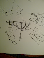
Below are sketches of my design or ideological conditions. I will start modeling tomorrow in class as I'm trying to figure out all the details tonight.

The second shows the general site and the 'T' intersection that would have the track built on. The two transmission towers are marked with an 'X' as this track would weave in and around the space below.


Alrighty 2116, gonna take 15.


Laterize.


Your buddy @


Quickview of the lookout

Just finished a really rough model of the walkway/lookout.  The biggest thing I noticed when modeling this is that I've spent too much time designing this in section, so it was good to try 3d.  A few notes about the images below: First of all, yes they're very rough.  The vertical(ish) steel armatures (in the electrical relay sense not the plaster sense) would be a plasma cut plate with a surrounding edge plate, so far I've only modeled the edge plate part but it's obvious there the cut plate would be.  The rotating/sliding connections would be circular HSS cuffs around smaller HSS tubes.  Colours: Black- canvas/other membrane material, Green- wood walkway surface, Red- fixed halves of the armatures, Blue- active armatures, Purple- HSS curved truss system, Teal- Ocean, Grey- terrain (note: extremely abstracted for preliminary modeling)  What's not here: well, lots, but mostly I have only modeled the downward pulling armatures.  They will be contrasted with upwards pushing armatures.  Each of the active armatures acts beween and opposite each other and between the fixed points (Red).

Plan 
Elevation, not very descriptive yet.
Side elevation (note: the person hiding in there for scale)
Here you can best see the lower membrane that provides the driving force for the active armatures
Finally, here's the section showing the downward pulling armature.  The wind is acting from the right, which is translated to a vertical motion on the other side of the walkway via two rotating connections and a sliding element.  The grey lines represent the other end of the range of motion.
Next up, I'm going to work out the other armature.  Designing the movement for these things is a lot harder than I thought it would be because I'm working on the assumption that the membrane (the top grey line in the image above) will not stretch within the plane of the section.  This, coupled with the translation of a circular motion to a vertical (mostly) linear movement is a tricky operation.
The other thing I'm planning on doing is putting all of this is in Grasshopper to parametize and simplify a few elements including the lengthwise  triangulation of the truss.  I also may include parameters to change the shape and angle of the walkway itself.  Finally I will be adding parameters to show the displacements of the armatures and the membranes to simulate the effects of the wind.

My geo lecture is done in a few minutes so I'd better finish up this post.

J

PS: I'm thinking that the walkway will have to widen at the center point (in plan) to provide a better lookout platform condition.  This would necessitate the creation of different armatures to allow for the extra cross-sectional width.


Bush update


 Proceeding onward with my greenhouse design, I found a general form that weaves through the concrete columns underneath the gardiner. The greenhouse itself will 'hover' 4m above grade and the only point that hits grade is on the west part of the building where an algae water filtering tank will reside to treat and filter collected water for irrigation.


In order to achieve this organic form, the surface will be divided accordingly and the steel members will essentially become the ribs of the building. I began working out some details, and figured out a preliminary sketch detail. Essentially the steel ribs will have two individual connections at the top that will mount to the top and side of the concrete highway slab. 

The second image is more of what the form of the steel ribs might begin to take shape. Still a lot to do for next week...ayeeeeeee 

Working Out The Details


Continuing with the design of a nature observatory I have begun to finalize the building form and think about the structural steel elements that will make it work.
The manipulation of points within a hexagonal frame became the logical steps which helped me realize one of my earlier sketches. 

From here I began to think about what type of structural systems I would use and quickly sketched out some possibilities. 

Taking this general idea of what I wanted I further developed my digital model and roughly designing the elements I want to have. The model is nowhere near completion, but it's a start. 

The model allowed me to think more about the steel details I want to employ and possible ways of solving structural issues. I am still uncertain about how some of these will work out in the design, but a little more research and reading will get me there.


Some concerns this far with the design are mostly structural (will this thing even stand up with the structure iv imagined?) but also aesthetic. Although I wanted the building to look light and have a high level of porosity it looks like just a tectonic frame waiting for something else to be added. Even though there is a lot more detail to add to the model which could fix this problem, I also began to look at some examples of architectural projects that use steel mesh.
Looking at the work of Dominique Perrault, who I remembered as the designer of the Berlin velodrom, I stumbled upon his design of a pedestrian footbridge.

The bridge uses a series of steel cables which do not limit the visibility within the structure, but from the exterior provide what looks like a cohesive surface. This might be an element to consider in my design...


Sunday, January 29, 2012

P1_progress_two

The site I have chosen to work with is the Finch TTC station. Specifically, it is the passenger pickup roundabout and the connection it makes with the commuter parking lot to the west.

I feel that a new structure could be put in place at this location because it is aging and unpleasant to look at. Although it is functional, there is room for improvement.

Nowadays the amount of waiting space is insufficient at peak hours. The vehicular traffic is unsafe for passengers crossing into the parking lot during busy hours and night time.

I am proposing to build an elevated waiting area which then links into a small elevated pedestrian walkway/bridge connected to the parking lot.


The highlighted location is the intended area of intervention.


Please do not take my drawings literally. No, I do not plan to put a death star above the passenger pick up. This is merely a conceptual drawing during the beginnings of design.


Currently, the connection where passengers walk up towards the waiting area is quite closed in. I would like to open up the space and allow natural light to penetrate the area.

The elevated passenger waiting area will be suspended above the transparent ground plane. I intend to create a light supporting structure. The triangulated structure for the waiting area will mostly remain. The structure for the pedestrian walkway is undecided.